Showing posts with label vector. Show all posts

Friday, April 1, 2011

Alternating Rounded Corners on Graphic Elements

I like legends that blend in with the neatline of a map but if there are disconnected graphical elements with rounded corners then a sharp corner will not match.

The solution is as simple as aligning graphical elements (drawing various shapes) and applying a Union process to make a single shape.

  • Begin by adding two Rectangle elements and either a Circle or an Ellipse element (holding Ctrl while dragging the boundary of an ellipse will create a circle by keeping the aspect ratio of the width and height equal; the same goes for drawing a square with the Rectangle tool) to the Layout view of an ArcMap project
Add two Rectangles and a Circle
  • Align the top of the circle with the tall rectangle and the right side of the circle with the wide rectangle.  This can be done by either using ruler guides or by selecting two objects and using alignment tools that may be on a toolbar, or by right clicking on the selected objects and choosing an alignment method from the Align sub-menu.
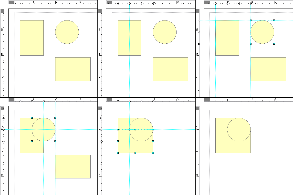
  • Once the objects are aligned, select all three elements, right click on them and navigate to the Graphic Operations menu, and choose Union to blend all three objects together into a single element
From this point one can scale the curve smaller, use smaller circles to create sharper corners or ellipses for more gradually curving ellipses, combine these elements with others, or use other Graphic Operations to create more advanced features (Intersect , Subtract ); some even with negative space (Remove Overlap).

The following is a quick example of a few of these methods.  The inset title box was flipped horizontally, and a couple of additional boxes were Unioned to extend the space for the scale bar.  The north arrow box was simply a circle with three quarters Subtracted from a digitized polygon.  Guides assisted the alignment for clean and even corners.

Note: Since these are vector graphics, the elements can be easily scaled with a clean look.  In some cases, however, if the shapes are not aligned together precisely, distortions can occur where two elements were joined together.

Friday, February 19, 2010

Gaps in Polyline Coverages / Vector Linear Direction

I'm editing a large statewide line coverage of streams across the state of Florida based on 24k NHD Flowlines. I have been continually coming across what appear to be small gaps in the coverage, however zooming in (even to 1:1 or further) does not reveal disconnected features.  Setting snapping parameters and repositioning the endpoints in an editing session doesn't help either.

Here's a screenshot with an enlargement of the gap to the left.  The instances of the gap are subtle, and even more so in screenshot below (click to enlarge):

A gap between two segments in a polyline coverage with
an enlargement of the issue to the left

It turns out that the line segments do in fact intersect and their ends are connected.  The problem is that the vector feature directions may not be aligned properly.  Although it is possible for two stream segments to flow away from each other (via confluence at usually obtuse angles), when the directions of two line segments are converging (see below) a small gap appears between the two features which is usually only one pixel wide.

There's a bit more to the distance and direction parameters that polyline features preserve in a vector dataset. A tertiary "from-to" designation is included in the bearing, although it's not always apparent at first glance (nor is it always needed, though it's a good idea to consider to avoid future problems).

Vector Linear Direction:

As an illustration, two simple line segments are created.  Line 1 is digitized from west to east / left to right, and Line 2 is digitized from east to west, however it isn't immediately apparent:


By viewing a line's vertices (double click on a line segment using the edit tool in an edit session to expose its sketch) one can view the from-to direction orientation of a line feature.  Initial / first, and intermediate vertices are green, and the final / last vertex is red; which indicate from-to direction:


The from-to direction of a line can be flipped easily: select a line, expose its sketch (double click using the edit tool), then right click the sketch and choose Flip from the context menu.

It's easier to visualize flow direction of a linear network by putting arrow heads on the end of each line:


Arrowhead Symbology:
  • Open the "Symbol Selector" dialog for a line coverage (change the symbol properties):
 
  • Click Properties to open the Symbol Property Editor
  • Change the Type to "Catrographic Line Symbol"
  • Navigate to the Line Properties tab
  • Select the middle, right facing arrow from Line Decorations area and click OK until you're back at your map:

The default symbology is a bit bulky so play around with different settings and characters to represent arrowheads or other symbols at either or both ends of your line features.

Linear Network Interactions:

So the single pixel-wide gap seems to appear only with converging line segments, and not with diverging, or in-line interactions: