Here's a screenshot with an enlargement of the gap to the left. The instances of the gap are subtle, and even more so in screenshot below (click to enlarge):
A gap between two segments in a polyline coverage with
an enlargement of the issue to the left
an enlargement of the issue to the left
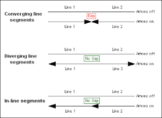
It turns out that the line segments do in fact intersect and their ends are connected. The problem is that the vector feature directions may not be aligned properly. Although it is possible for two stream segments to flow away from each other (via confluence at usually obtuse angles), when the directions of two line segments are converging (see below) a small gap appears between the two features which is usually only one pixel wide.
There's a bit more to the distance and direction parameters that polyline features preserve in a vector dataset. A tertiary "from-to" designation is included in the bearing, although it's not always apparent at first glance (nor is it always needed, though it's a good idea to consider to avoid future problems).
Vector Linear Direction:
As an illustration, two simple line segments are created. Line 1 is digitized from west to east / left to right, and Line 2 is digitized from east to west, however it isn't immediately apparent:
By viewing a line's vertices (double click on a line segment using the edit tool
 in an edit session to expose its sketch) one can view the from-to direction orientation of a line feature. Initial / first, and intermediate vertices are green, and the final / last vertex is red; which indicate from-to direction:
 The from-to direction of a line can be flipped easily: select a line, expose its sketch (double click using the edit tool), then right click the sketch and choose Flip from the context menu.
It's easier to visualize flow direction of a linear network by putting arrow heads on the end of each line:
Arrowhead Symbology:
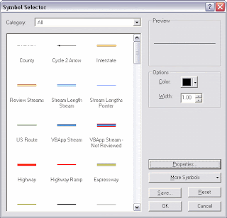
- Open the "Symbol Selector" dialog for a line coverage (change the symbol properties):
- Click Properties to open the Symbol Property Editor
- Change the Type to "Catrographic Line Symbol"
- Navigate to the Line Properties tab
- Select the middle, right facing arrow from Line Decorations area and click OK until you're back at your map:
The default symbology is a bit bulky so play around with different settings and characters to represent arrowheads or other symbols at either or both ends of your line features.
Linear Network Interactions:
So the single pixel-wide gap seems to appear only with converging line segments, and not with diverging, or in-line interactions:


No comments:
Post a Comment